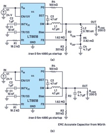
05701-A-0325 LTspice test circuit using W ü rth REDEXPRESS data

The output ripple voltage of the step-down converter is a function of the capacitance impedance and inductance current. To achieve better simulation accuracy, W ü rth REDEXPRESS can be used to select a 4.7 µ F output capacitor (885012208040) and extract ESR and ESL that vary with frequency. ESL and ESR are sometimes loaded into the LTspice capacitance model, but a quick check will prove that the LTspice capacitance data often ignores ESL. Figures 3a and 3b show two equivalent circuits: (a) using a 4.7 µ F output capacitor and discrete ESL and ESR values; (b) Use W ü rth capacitors containing ESR and ESL parameters.

Figure 3 LTspice test circuit: (a) Using 4.7 μ F capacitance and discrete ESL and ESR values; (b) Using W ü rth capacitors containing ESR and ESL parameters
REDEXPRESS displays the impedance of many components that vary with frequency to help determine the critical parasitic effects of each passive device. These parasitic values can be implemented later in the LTspice model, allowing for individual evaluation of their contribution to the total voltage ripple.
As mentioned earlier, LT8618 provides very low output ripple with peak to peak values less than 10 mV. However, when simulating the effects of capacitive loads and ESL, the output ripple voltage is 44 mV p-p. Within the frequency range, the contribution of capacitor ESL to noise is quite significant, as shown in the FFT diagram in Figure 4.
To evaluate EMC compliance in conduction settings, most standards rely on Line Impedance Stability Networks (LISNs) or Artificial Power Networks (AMNs). These devices have similar functions, located between the circuit power supply and the device under test (DUT) – in this case, the buck converter. LISN/AMN consists of low-pass and high pass filters. A low-pass filter provides a path from a low-frequency power source (DC to several hundred hertz) to the DUT. High pass filters are used to measure power and return power line noise. These voltages were measured on a 50 Ω resistor, as shown in Figures 5 and 61. In actual laboratories, this voltage is measured using an EMI receiver. LTspice can be used to detect noise voltage and plot conducted radiation test spectra.
Conducted radiation can be divided into two types: common mode (CM) noise and differential mode (DM) noise. It is important to distinguish between CM and DM noise, as EMI mitigation techniques may be effective for CM noise but ineffective for DM noise, and vice versa. Due to the simultaneous output of V1 and V2 voltages, LISN can be used to separate CM and DM noise in conducted radiation testing, as shown in Figure 6
DM noise is generated between the power line and return line, while CM noise is generated between the power line and the ground reference plane (such as a copper test bench) through the stray capacitor CSTRAY. CSTRAY actually simulates the parasitic effect of switching noise at the output of a step-down converter.
The LTspice LISN circuit corresponding to Figure 6 is shown in Figure 7. In order to achieve higher simulation accuracy, L5 and L6 inductors are used to simulate the inductance of the LISN power supply lead to the test circuit. Resistance R10 simulates the impedance of the slotted ground layer on the test board. Figure 7 also includes capacitor C10 for simulating CSTRAY. Capacitor C11 simulates the parasitic capacitance between the sensor PCB and the sensor mechanical housing.
