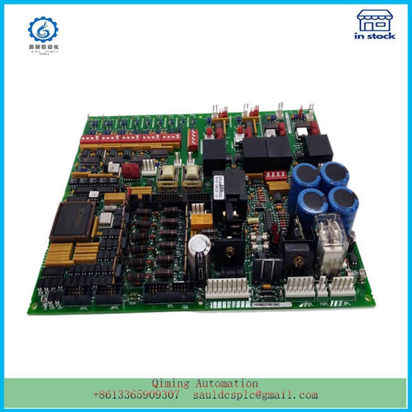
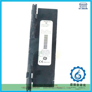
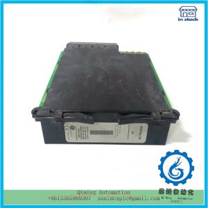
DS200DCFBG1BNC | GE | Voltage and current dual loop control
¥8,555.00
Module Number: DS200DCFBG1BNC
Product status: Discontinued
Delivery time: In stock
Product status: 100% new
Sales country: All over the world
Product situation: one year warranty
Contact me: Sauldcsplc@gmail.com +8613822101417 SIMON
Have a good day! Thanks for watching my website!
TRICONEX 3721
A-B 1797-PS2E2/A
ABB 1MRK002122-ABR02
ABB 1MRK002133-ABr02
FOXBORO P0972SE
GAI TRONICS 10959-201
Traco TIS600-148
ABB PM864AK01 3BSE018161R1
ELAU SM070-60-010-P0-45-S1-B0
TRICONEX 3000656-210-REVA
ABB RET543AM243AAAB
Description
DS200DCFBG1BNC | GE | Voltage and current dual loop control
- .Many products are not yet on the shelves please contact us for more products
- .If there is any inconsistency between the product model and the picture on display, the model shall prevail. Contact us for the specific product picture, and we will arrange to take photos in the warehouse for confirmation
- .We have 16 shared warehouses around the world, so please understand that it can sometimes take several hours to accurately return to you. Of course, we will respond to your concerns as soon as possible
The control concept of DS200DCFBG1BNC is: UC3875 outputs 4 PWM pulses and controls VT1 to VT4 in the main circuit through the driving circuit. The output DC bus voltage is compared with the internal standard signal of UC3875 through the signal acquisition circuit, and the phase difference of the four PWM output pulses is adjusted to stabilize the output. After the input current passes through the signal acquisition circuit, it is compared with the overcurrent protection signal threshold inside UC3875. Once overcurrent occurs, UC3875 locks and trips, and DC/DC stops working, completing the input overcurrent protection.
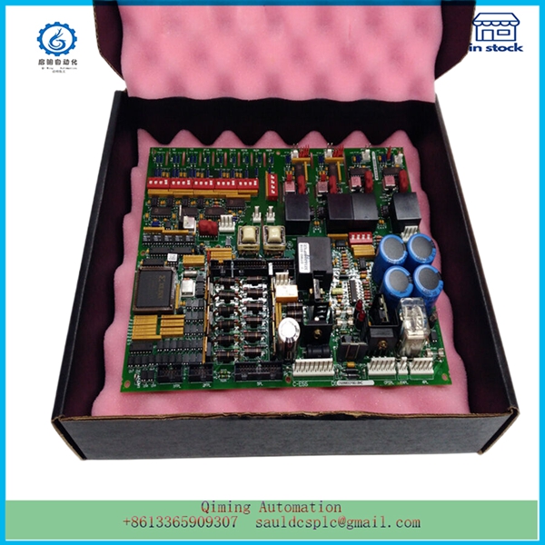
Due to the significant difference in the state of the DS200DCFBG1BNC system when the inverter system operates in independent and grid connected modes, two different control methods are required.
When the inverter operates independently, voltage control mode is adopted, and the control block diagram is shown in Figure 3a. The control idea is: after sampling feedback, uo is compared with the sine wave reference voltage signal uref, the error signal is adjusted by PI, and then the corresponding driving signal is generated by the SPWM generator, which is sent to the main circuit to drive the switching transistor. The system transfer function can be obtained from the control block diagram as follows:
According to control theory, DS200DCFBG1BNC requires sufficient gain in the low frequency range to improve the stability performance of a closed-loop system; The mid frequency band should cross the horizontal axis at -20 dB/dec to ensure sufficient phase margin; The high-frequency range needs to be rapidly lowered to improve anti-interference ability.
-
Please contact us for the best price. Email: 【sauldcsplc@gmail.com】
-
For more products, click here
Mailbox:sauldcsplc@gmail.com |DS200DCFBG1BNC
www.abbgedcs.com | Qiming Industrial Control | Simon +86 13822101417

Reviews
There are no reviews yet.