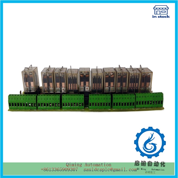
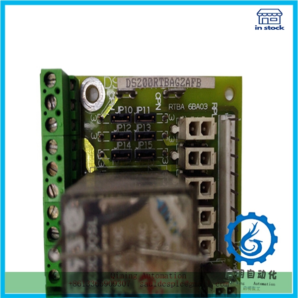
DS200RTBAG2AFB | GE | Assembly guide rail module
¥4,811.00
Module Number: DS200RTBAG2AFB
Product status: Discontinued
Delivery time: In stock
Sales country: All over the world
Product situation: Brandnew , one year warranty
Contact me: Sauldcsplc@gmail.com +8613822101417 SIMON
Have a good day! Thanks for watching my website!
Introduced Product:
60WKS-M240/22
6SM37L-4.000
705-1512-01
8101-HI-TX-02
8106-TI-RT
8115-DO-DC
8121-DI-DC
84-W8559F01B
8421-CC-PS
8521-LC-MT
Description
DS200RTBAG2AFB | GE | Assembly guide rail module
- .Many products are not yet on the shelves please contact us for more products
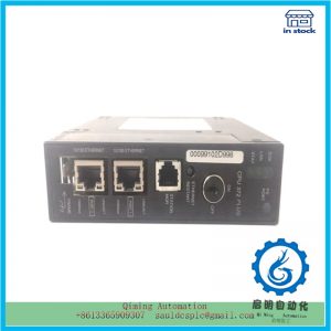
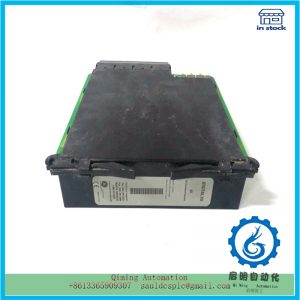
- .If there is any inconsistency between the product model and the picture on display, the model shall prevail. Contact us for the specific product picture, and we will arrange to take photos in the warehouse for confirmation
- .We have 16 shared warehouses around the world, so please understand that it can sometimes take several hours to accurately return to you. Of course, we will respond to your concerns as soon as possible
DS200RTBAG2AFB is a PLC designed for medium to high-end performance ranges, featuring modular and fanless design, durability, easy scalability, and extensive communication capabilities, as well as easy implementation of distributed structures and user-friendly operating interfaces.
1. Installing assembly guide rails
DS200RTBAG2AFB long assembly guide rail for installation, and the specific steps are as follows:
(1) Cut the assembly guide rail with a length of 2 meters to the required length.
(2) Mark four holes for installing fixing screws and one hole for protecting conductor bolts.
(3) If the length of the guide rail exceeds 830 mm, additional holes must be provided to secure it with more screws. Mark these holes along the groove in the middle of the guide rail (as shown in Figure 1), with a distance of approximately 500 mm between them
① Holes for grounding wire bolts; ② A groove for drilling additional holes for installing screws; ③ Holes for installing screws;
④ Additional holes for installing screws; ⑤ Holes for installing screws
DS200RTBAG2AFB Guide Rail Installation
Reference address for this article: http://www.eepw.com.cn/article/201612/331128.htm
(4) Drill out the marked holes, and the aperture of the M6 screw is 6.5+0.2mm.
(5) Install an M6 bolt to secure the grounding wire.
(6) Confirm the PLC clearance after installing the guide rail (as shown in Figure 2).
Mailbox:sauldcsplc@gmail.com |DS200RTBAG2AFB
www.abbgedcs.com | Qiming Industrial Automation| Simon +86 13822101417
We may provide the information of this product:
Guidance manual PDF /Datasheet/ Weight/ Size/ Orignal country/ Prodcuct COO & COM & COC
Certificate of conformity / Certificate of Origin / Certificate of Origin /Operation method
Delivery time/ Provide a one-year warranty / Brand New Original Authentic

Reviews
There are no reviews yet.