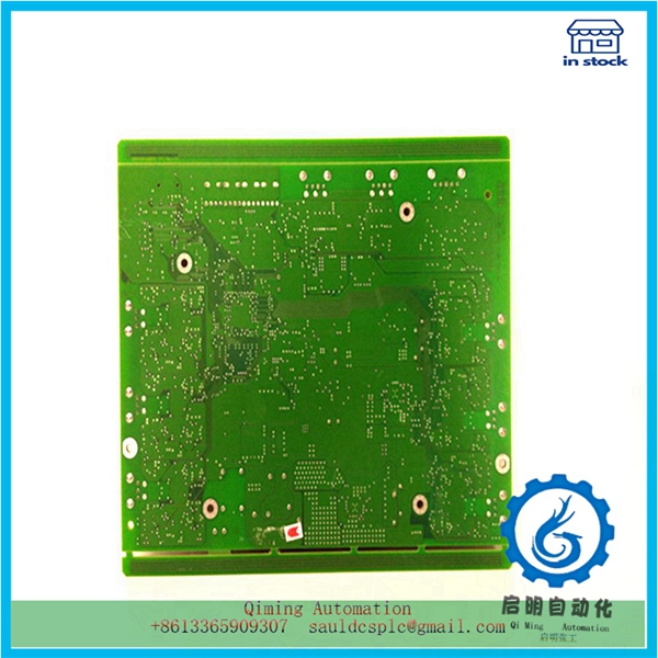
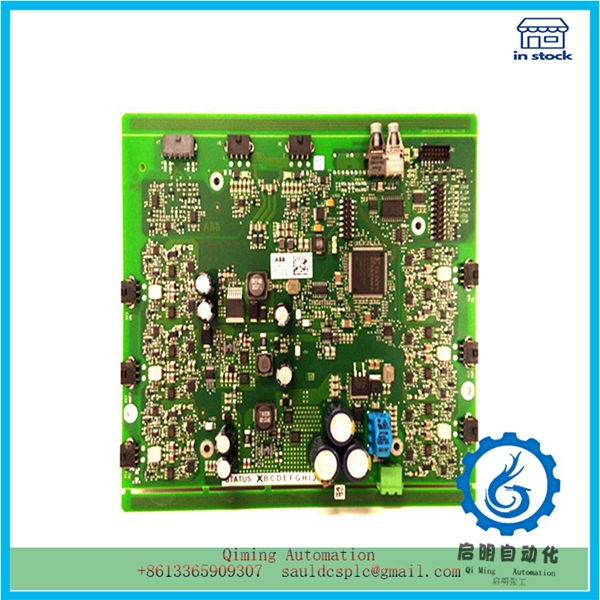
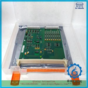
GCC960C102 3BHE033067E0102 | ABB | bridge power switches board
¥5,252.00
Module Number: GCC960C102 3BHE033067E0102
Product status: Discontinued
Delivery time: In stock
Sales country: All over the world
Product situation: Brandnew , one year warranty
Contact me: Sauldcsplc@gmail.com +8613822101417 SIMON
Have a good day! Thanks for watching my website!
Introduced Product:
4352B
D136-001-007
IS200VCMIH2BEE
PM866AK01
INTELLISCANDE14-405NM SCANLAB
A02000-LS25
PFTL101B 5.0KN 3BSE004191R1
RPS AX7695
1S200BPVCG1BR1
PFSK152
IS215UCVEH2AE
D136-001-007
VMIVME-7750
Description
GCC960C102 3BHE033067E0102 | ABB | bridge power switches board
- .Many products are not yet on the shelves please contact us for more products
- .If there is any inconsistency between the product model and the picture on display, the model shall prevail. Contact us for the specific product picture, and we will arrange to take photos in the warehouse for confirmation
- .We have 16 shared warehouses around the world, so please understand that it can sometimes take several hours to accurately return to you. Of course, we will respond to your concerns as soon as possible
The Triac dimmer should be connected to the GCC960C102 power phase line L (see Figure 4). R1 is a fusible resistor used for short-circuit protection and transient current limitation during startup. D1~D4 are bridge rectifiers, with R3, C1, R2, L1 and their subsequent L2 and C3 at the input end forming an electromagnetic interference (EMI) filter. Diodes D5, D6, and capacitor C12 form a charge pump circuit. MOSFETs (T1 and T2) are half bridge power switches. The secondary windings L10A and L10B of inductor (choke) L10, as well as capacitors C14 and C15 connected in series to the filament, are used for filament preheating. The D50, D51, C52, C50, R51, and C51 connected to the filament below the right end of the CFL form the lamp current detection and feedback circuit. The position detection circuit of the dimmer potentiometer knob is composed of R40, R41, C40, C42, D40, D41, R43, and C41 connected between the output terminal of the bridge rectifier and the CS+pin of IC1 (UBA2014). R43 and C41 form the dimmer potentiometer knob position detection circuit. Compare the detection voltage on pin CS – of IC1 with the control voltage on pin CS+to control the half bridge frequency and adjust the lamp current, thereby achieving dimming.
After the system is powered on, the GCC960C102 bus voltage on capacitor C7 is charged to capacitor 31 through starting resistors R30 and R31. When the voltage on pin VDD of IC1 exceeds 13V, the oscillator begins to oscillate at the highest frequency fmax.
The fmax value is determined by the external capacitance C23 (100 pF) on pin CF of IC1 and the resistance R21 (33 k Ω) on pin IREF
Mailbox:sauldcsplc@gmail.com |GCC960C103 3BHE033068P106
www.abbgedcs.com | Qiming Industrial Control | Simon +86 13822101417
We may provide the information of this product:
Guidance manual PDF /Datasheet/ Weight/ Size/ Orignal country/ Prodcuct COO & COM & COC
Certificate of conformity / Certificate of Origin / Certificate of Origin /Operation method
Delivery time/ Provide a one-year warranty / Brand New Original Authentic

Reviews
There are no reviews yet.