PMC422FP |FORCE| Analyze the PLC control process
¥8,544.00
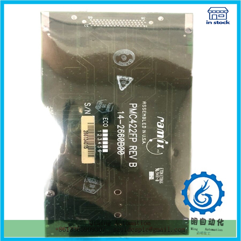
Module number: PMC422FP
Product status: Discontinued
Delivery time: In stock
Sales country: All over the world
Product situation: Brandnew , one year warranty
Contact me: Sauldcsplc@gmail.com +8613822101417 SIMON
Have a good day! Thanks for watching my website!
Introduced Product:
ABB UFC765AE102 3BHE003604R0102
ABB MEM86-3×192/CMBMR3
ABB 5SYN-5100A-Z,V221 3BHB006717R0221
REXROTH CML40.2-SP-330-NA-NNNN-NW
BENTLY 3500/15 106M1079-0
ABB 07KT98 GJR5253100R0278
YOKOGAWA NFAI841-S00
BENTLY 106M1081-01
ABB AO910
KOLLMORGEN S70602-PBNANA
ABB PM864AK01 3BSE018161R1
NI SBRIO-9607
TRICONEX MA2211-100
Description
PMC422FP |FORCE| Analyze the PLC control process
Figure 5-2 shows the PMC422FP wiring diagram, and Figure 5-3 shows the control ladder diagram. Figure 5-4 illustrates the execution process of the program for each scanning cycle. Although button SB2 is not used in the program, its status still affects the status of its corresponding internal input relay. In Figure (a), ① during the scanning process, the states of the two buttons are scanned and stored in their image area. Since SB2 is a stop button, even if it is not pressed, its input circuit is still closed. Therefore, X1 stores “1” (ON state), while the other bits store “0” (OFF state). ② Execute the program process, and the program calculates based on the internal relay status corresponding to the number of contacts used. Due to X0 being in the OFF state, the corresponding moving and closing contacts are in the open state.
The calculation result is that Y0 and Y1 are in the OFF state, and the result is stored in the output image area, that is, Y0 and Y1 are stored as “0” The output refresh process drives the output device based on the status of each member in the image area. As the output image area is in the OFF state, the output indicator light cannot form a closed loop and does not light up. If the input does not change, the state of the internal relay remains unchanged. In Figure (b), after pressing the SB1 button, the X0 input circuit is closed. ① Input scanning stores the input status in its image area, and both PMC422FP and X1 are stored as “1”. ② Execute the program process, following the principle of left to right and top to bottom, one by one. ( http://www.diangon.com/ On the first line, the X0 contact is closed, but at this time, the Y1 contact is in a “0” state. Therefore, the Y1 contact is in an open state, and Y0 cannot conduct, resulting in a “0” state. In the second line, the X0 contact is closed, so the status of Y1 is “1” During the output refresh process, due to Y1 being in a conductive state, light 2 is on.

Reviews
There are no reviews yet.