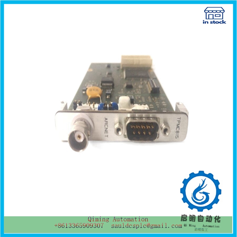
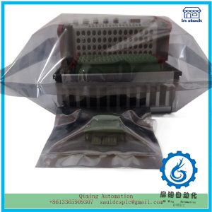
TPMC815-11 | Tews Technologies | Switching signal line
¥8,858.00
Module Number: TPMC815-11
Product status: Discontinued
Delivery time: In stock
Sales country: All over the world
Product situation: Brandnew , one year warranty
Contact me: Sauldcsplc@gmail.com +8613822101417 SIMON
Have a good day! Thanks for watching my website!
Introduced Product:
ALSTOM LE109A-1
ALSTOM AM164
ALSTOM IR139-1
ALSTOM AL132
ALSTOM LC105A-1
ALSTOM BGTR8HE 24491276A1004
ALSTOM PIB100G 3BEE0226
ALSTOM PIB102A 3BEB0180
ALSTOM PIB310 3BHB0190
ALSTOM PIB1201A 3BEC0067
ALSTOM 43297029
ALSTOM EP3-E-4-A
AMCI 7264
Description
TPMC815-11 | Tews Technologies | Switching signal line
The wiring of the TPMC815-11 control system includes power lines, input/output lines, power lines, and grounding wires. Improper wiring can cause interference such as electromagnetic induction and electrostatic induction, so it must be wired according to specific requirements. The power cable is a high-voltage and high current line, and the wiring of the PLC system may be interfered with when it is close. Therefore, when wiring, the input/output lines of the TPMC815-11 should be separated from other control lines and not shared with the same cable. The switch signal line and analog signal line should also be wired separately, and the latter should use shielded wire and the shielding layer should be grounded. Digital transmission lines should also use shielded wires and the shielding layer should be grounded. When external wiring, control cables, power cables, and input/output lines should be separated and wired separately, with a distance of generally more than 30cm between them. When the actual situation only allows wiring in the same slot, metal plates are used to separate and shield the control cables, power cables, and input/output lines, and the metal plates must also be grounded. The power line on the secondary side of the isolation transformer should use copper core polyvinyl chloride insulated twisted pair flexible wire with a diameter of at least 2mm2. The power lines, input/output lines, and power lines processed in this way can reduce external magnetic fields and mutual interference.
Anti interference measures during installation
The environment in which the TPMC815-11 control system is located also has a certain relationship with its own anti-interference, so the following aspects should be paid attention to during installation.
① Filters and isolation regulators should be installed at the power inlet of the PLC control cabinet to prevent interference from entering the cabinet or to minimize the distance between the incoming lines.
② The PLC control cabinet should be kept as far away as possible from high-voltage cabinets, high-power equipment, and high-frequency equipment.
③ PLC should be kept as far away as possible from electromagnetic coils such as relays and contacts that are prone to arcing.
④ PLC should be kept away from heating electrical equipment or other heat sources and placed in a well ventilated location.
⑤ The external of the PLC should have reliable waterproof measures to prevent rainwater from entering and causing machine damage.

Reviews
There are no reviews yet.